
How to Block Drones with a Drone Jammer
In an age where the sky is dotted with drones, the importance of drone jammers has never been more significant. From commercial deliveries to personal


Here’s a step by step guide on how to build your own GPS jammer. Below are the main steps we are going to introduce in this article:
| Step 1 | Required Components & Materials |
| Step 2 | Building the Circuit |
| Step 3 | Incorporating a VU Meter |
| Step 4 | Testing Your GPS Jammer |
To undertake this project, you’ll need to assemble a variety of components. The list below details each item along with a brief explanation of its purpose.
| Component | Function |
| NE555 Timer IC | Integrated circuit for creating waveforms and time delays. |
| 47 pF Ceramic Capacitor | Capacitor for storing and releasing electrical energy to stabilize voltage. |
| 0.01 μF Ceramic Capacitor | Capacitor for storing and releasing electrical energy to stabilize voltage. |
| 10 KΩ Resistor | Resistor to limit electrical current flow and set currents. |
| 220 Ω Resistor | Resistor to limit electrical current flow and set currents. |
| 100 μF Electrolytic Capacitor | Capacitor with high charge storage capacity to smooth out voltage fluctuations. |
| Red LED | Light-emitting diode used as a signal or power indicator. |
| 9-Volt Battery | Power source for the assembled components. |
| Breadboard | Device for prototyping and testing circuit designs without soldering. |
| GPS Receiver Module and Antenna | Components used for testing the effect of the assembled circuit. |
The breadboard will be your primary workspace for this project. It provides a convenient platform for testing your circuit without requiring any soldering.
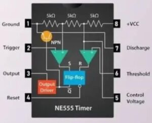
Begin by inserting the NE555 timer IC onto the breadboard. Follow the schematic diagram to place each resistor, capacitor, and LED in their correct positions. Use jumper wires to establish the necessary connections between them.
Power the circuit with the 9-volt battery. If the red LED lights up, it indicates that the circuit is functioning correctly and generating the desired radio frequency signal capable of disrupting the GPS frequencies.
A Volume Unit (VU) meter measures and displays the strength of the radio frequency signal your circuit generates. Follow below step to install your VU meter.
Place the VU meter’s input terminals in line with the output of your jammer circuit. This will allow the meter to capture the exact strength of the signal being emitted. Ensure the connections are secure to avoid inaccurate readings. Once integrated, power up your circuit. The VU meter’s needle or LED indicators should respond, displaying the signal’s strength in decibels (dB). Familiarize yourself with the readings. A higher dB indicates a stronger signal.
Some VU meters allow for calibration. This ensures that you get precise readings, optimizing the performance of your GPS jammer.
Testing is the final step in your project. Prior to testing, ensure your environment is safe and free from sensitive electronic devices to avoid unintended interference. Than following below process to test your jammer.
Turn on the jammer and observe any indicators (like the red LED) for feedback on its operational status. Use a GPS receiver module or device with GPS functionality for testing. Ensure the device has a clear signal before introducing the jammer. Monitor the GPS device as you bring the jammer closer. Signal disruption or loss indicates the jammer is working. Look for signs like slower update times on the GPS module or a “searching for signal” status. There might be a noticeable drop in the number of satellites the GPS module detects.
While building a GPS jammer can be an intriguing DIY project, it’s important to be mindful of the legal and ethical considerations. GPS jammers are illegal in many countries, including the United States, due to their potential to interfere with essential communication networks and emergency services. Always prioritize safety and responsible use of technology.
In an age where the sky is dotted with drones, the importance of drone jammers has never been more significant. From commercial deliveries to personal

Protect your vehicle’s location privacy with a professional guide on GPS jammers. From selection to legal considerations and installation tips, we’ve got you covered. Key
Here’s a step by step guide on how to build your own GPS jammer. Below are the main steps we are going to introduce in

If you need a signal jammer, the easiest way is to purchase it online. Jammer Master is a professional signal jammer supplier. We have offered

You must have heard or seen in the media about the bugs. They are tiny devices that overhear cell phone conversations, hidden microphones, cameras and

The signal jammer can help us block any signal you dislike. Most of our jammers can block the signal from 10 to 500 meters. If

The phones we use daily need a signal to make a phone call with our loved ones, check out your friend’s recent activities on social